Ken Harker WM5R
Super CMOS Keyer III


Image of Super 
CMOS Keyer III at N5XU
The Super CMOS Keyer III at N5XU

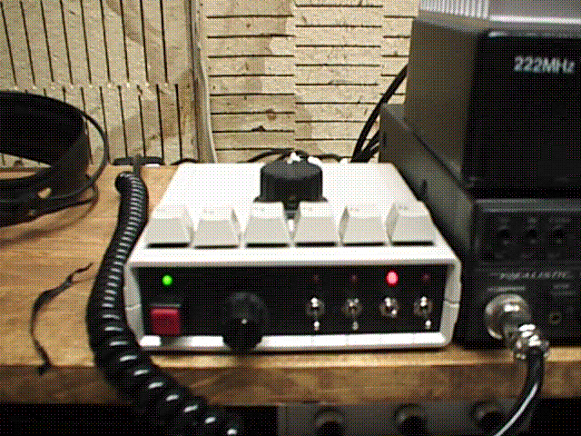
In 1998, I built a Super CMOS Keyer III for the VHF contest station at N5XU. The CMOS Super Keyer III is a partial kit sold by Idiom Press. The keyer internals were designed by KC0Q and N0II, as published in the August 1995 QST, p. 26.

The partial kit, as it comes from Idiom Press, contains a printed circuit board (PCB) and all the parts needed to populate it, including two integrated circuits (ICs). The builder needs to provide at least an enclosure, buttons, a knob, a potentiometer, wiring, a power source, and connectors. I designed mine to work with multiple radios, so I added additional parts, such as microswitches and LEDs.

One of the radios with which the keyer was intended to be used was an Yaesu FT-290R, a two meter all-mode radio that was used as an IF rig for a 1296 MHz transverter. The Yaesu FT-290R does not do even semi-break-in keying; in CW mode, you need to close a PTT line to switch the radio from receive to transmit. The Super CMOS Keyer III does not have a PTT output, but Dale Martin KG5U suggested a circuit that, when added to the Super CMOS Keyer III, would do the next best thing:


The PTT Circuit

PTT Mod by Dale Martin 
KG5U
The modification circuit, shown with and without the reed relay. Click to enlarge.

Dale Martin KG5U suggests: "What about a time-delay circuit that closes on the first dit and because of the RC time constant, holds the circuit closed until an (adjustable) time period after the last dit or dah. Let's see if I can describe this:

"The keyer output (pin 19) goes high to turn on the keying transistor. That positive voltage will cause the diode to conduct, charging up the capacitor and turning on the delay transistor. When the keyer output drops to zero (character or element space, no keying, etc.) the diode stops conducting. The wiper of the 50 Kohm potentiometer is set so that the discharge current of the capacitor through the transistor keeps the transistor open until the voltage at the wiper drops to around 0.7 volts DC. While the wiper voltage is above 0.7 volts DC, the transistor stays on...or conducting. This is the PTT line."

I followed this pretty closely, substituting a 150 ohm resistor for the 120 ohm resistor (because I had one), substituting an MPS2222A transistor for the 2N2222 (because I had one) and substituting a 47 Kohm microsize potentiometer for the 50 Kohm potentiometer. Because I was adding the circuit to a completed keyer, I didn't have the panel space to add another knob for adjustment of the PTT delay. I chose to use a microsize potentiometer, which fits nicely on the small PCB I used, and I was able to find the adjustment that I feel works well for the range of keying speed I normally use on VHF. If I ever need to readjust it, though, I will need to open up the case.

Mod Parts List


Last Updated 26 June 2020
wm5r@wm5r.org